|
|
|
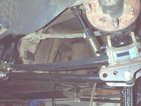
After reading about my homemade tube shock setup, you'll see I've gone with Doug Jackson's tube shock setup. Why? You'll also note I'm using his composite springs, anti-tramp bars and panhard bar. To put all those items together, I had to use his shock absorber bracket (anti-tramp bars would only work in conjunction with composite springs if I used it). So, at that point, the only thing left from my homemade setup was the upper tube shock mount. What the heck, a phone call to Doug & his upper mounts were on order. As I'm going with a Hawke's Cars coil-over front suspension that replaces the original shock with a custom upper control arm, I also decided to match the shocks front and rear. Thus, I also decided to go with GAZ adjustable coil-over tube shocks in the rear to match those coming from England. I won't use a coil-over spring in conjunction with the shock unless I need a small helper spring for the composites (I'm sure the composite springs will do their job, but I now have a backup).
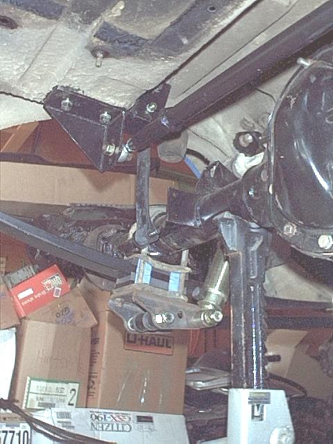
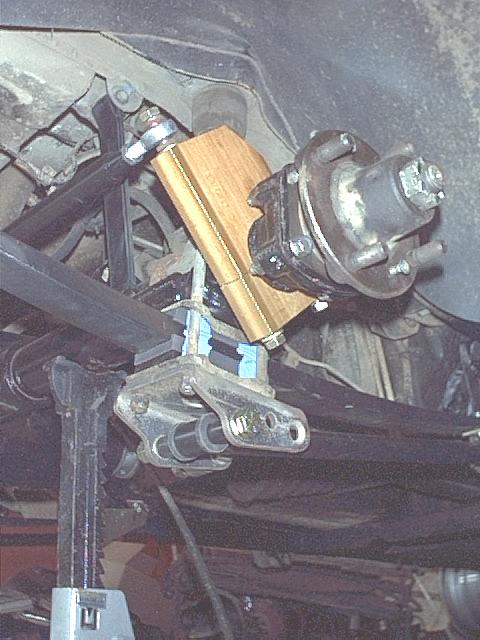
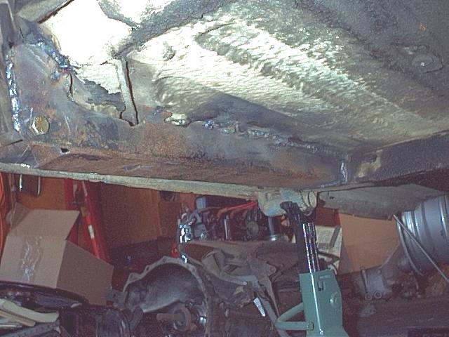
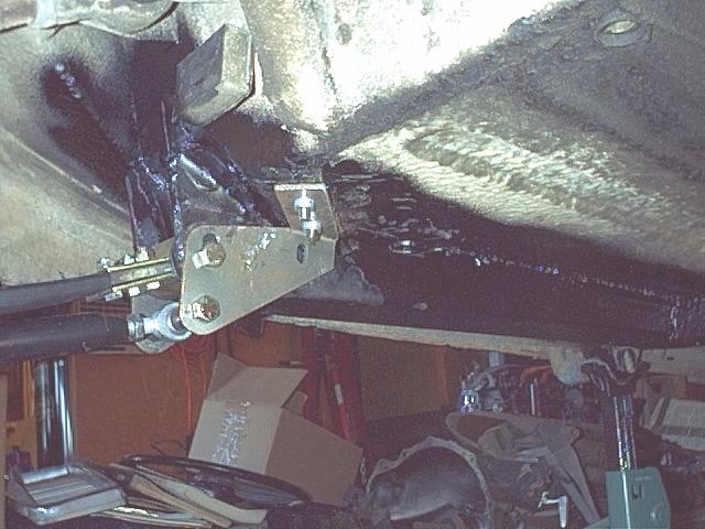
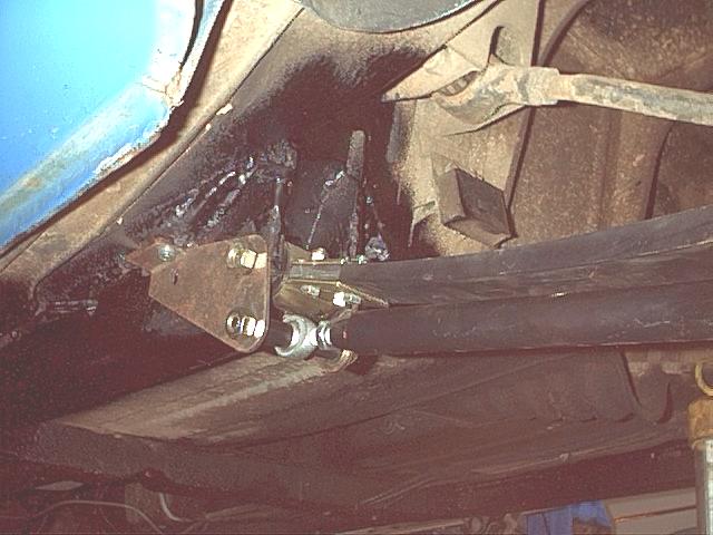
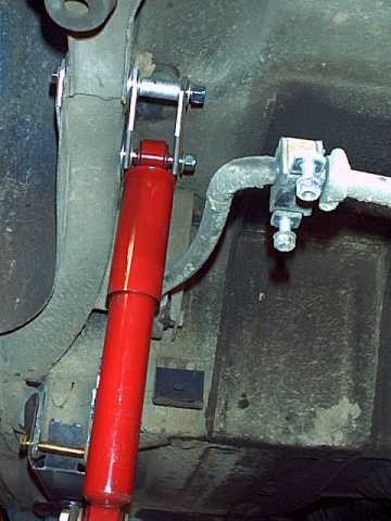
And, here's what I've learned about controlling spring roll-up (or hop) and rear end movement: Doug Jackson of British Automotive sent me a set of his new traction bar brackets to see if they will work in conjunction with my top hats. His panhard kit is complete and ready for distribution so it will be one of my major purchases; and, his anti-tramp bars are almost ready for the market. If his brackets fit, I'll install a set of his new V8 anti-tramp (traction) bars along with tube shocks. Here's a couple of photos of one of the brackets attached to the top hats. It shows the relationship of the spring to the anti-tramp bar.
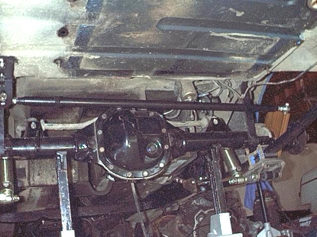
There's still one bolt to put in the rear of the bracket to complete the installation, I've gotta get a long 21/64" drill bit that'll go completely through the top hat to do that. And, the panhard bar and anti-tramps are now installed.....FINALLY!!!
The only difficulty I ran into during the actual installation was adapting the anti-tramp and composite spring hanger brackets to my top hats. Other than that, installation of both the anti-tramp bars and the panhard bar were a piece of cake. Should any of you choose to go the same route, simply follow Doug's instructions and you'll be finished with the installation of both over a long weekend. If things look a bit out of whack in the photos, its because I've not torqued any of my modifications down; they're in place but waiting toil I can work the suspension into its normal stance. To do that, I'll put her down on all 4 wheels and roll her around a bit so everything settles into place. Then, I'll level the panhard bar to a spirit level, and torque everything in place with the car on its wheels, not jacked up. While the rear end is out for its rebuild/modifications {MGC gears in MGB case), I'll also drop the fuel tank and install a modified one under the center of the trunk area so I'll have room for dual exhausts. Ah, the fuel tank. Moving it to the center of the car from its rightward position creates enough room to run dual exhausts from the engine to the rear of the car down both sides of the gas tank while keeping them high enough not to drag. After all, what’s a V8 car without dual pipes poking out from under the rear valance? However, moving the tank presents a few problems. To move the tank, new bolt holes have to be drilled in the trunk floor. That will be easy enough. The hard part comes when I cut the trunk floor to move the filler neck opening over to fit the new tank location. Cutting and relocating the original filler opening in the trunk floor is easy. But, as I want the trunk floor to look original, I'll have to rebuild some of the raised areas back into the floor where I make my cuts and patches before prepping for paint. Since I also want to maintain the original fuel filling location on the outside of the car with the tank moved approximately 3", I have to devise a new fuel delivery setup using a curved gas filler tube and an angled tank filler hose. I will probably follow Mike Cook's lead and use aviation fuel hose to make the connection between the original fuel filler location in the body and the new tank location in the trunk floor. This is also a good time to send the fuel tank out to be cleaned and have the fuel sending unit moved. Oh, I'm using a '65-'69 non-vented tank as I don't plan to go the fuel injected route. Running dual exhausts on both sides of the car puts a tailpipe too close to the fuel sending unit. So, my plan is to move the unit to the front of the tank aka what Nick Smallwood did on his MGBGT V8 conversion with Sebring body kit and Jaguar XJ6 suspension web site. (Wow! And, I thought I was "the" autoist! If you want to see some serious MG modifications, visit his site.) There's a flat place on the front center of the tank where the height of the tank is the same as at the original sending unit location on the side. Placing the unit there and at the same height from the top of the tank as where it originally was means no modifications to the sending unit itself. At the same time as we were moving the sending unit, I had the tank boiled and relined. Here's what that modified tank looks like.
So here's the procedure for centering the gas tank under the trunk floor: 1. Make a brown paper template of the top of the gas tank, marking each hole location. Don't forget to mark the inlet tube location: make that hole the same size as the large one in the trunk floor through which the tube protrudes.
2. Place the gas tank template over the trunk floor so that the holes in it and the factory gas tank bolt holes in the trunk floor line up. 3. Move the template 3-1/4" to the left and mark the new bolt hole locations and the new inlet tube location. 4. Start with a 1/8" drill bit and make 10 guide holes--4 on each side & 2 along the back of the car. 5. Move upwards in bit sizes re-drilling the holes until the last size is 1/2". Don't forget to sand off any metal residue from your drilling. 6. Under the car, cut off the 2 studs on each side that protrude through the trunk floor to hold the gas tank. With an orbital sander, grind them flush with the trunk floor. 7. Cut the rear exhaust hanger bracket off flush with the rear valance as : a. its in the wrong place after the tank is moved, and b. it interferes with the movement of the tank. 8. Cut a large rectangle out of the trunk floor from the right edge of the flat part of the floor to about 1" left of where you marked for the new location of the fuel tank inlet tube.
9. From underneath the trunk floor, align the gas tank with the new holes. 10. From inside the trunk, and using 5/16"x1" fine thread bolts with a flat washer large enough to cover the 1/2" hole, run the bolts through the gas tank holes that have threaded hardware attached to them (2 on each side & the 2 in the rear). Finally, put 4 bolts through the holes that earlier were where studs went & attach them from underneath using flat washers, lock washers, and nuts.
11. Spot weld the 4 gas tank side bolts that were attached using nuts in #10 above--not those attached using hardware integral to the tank--so that they replicate the studs that were permanently protruding through the trunk floor. 12. Finally, weld the large square of trunk floor around the gas inlet tube and, using welding washers, fill all original holes. PHOTO 13. And, the last thing is to form a piece of aircraft hose to go between the gas tank inlet tube and the filler neck ferrule. PHOTO 14. Then, remove everything, clean and undercoat the trunk floor above the gas tank, and reinstall the gas tank making sure you use some type of body sealer under all the flat washers. 15. Last, sand the trunk floor to remove any evidence of welding; and, using body putty, reform the ends of the raised ribs cut and replaced during the project. PHOTO Now, all that's left is to paint the trunk floor. Oh, if you're gonna use a vented gas tank system, you'll have to cut the hole for the vapor separator to gas tank hose. Me? Not emissions control #1 will be in this baby! I'm going with an early vented gas cap. I said, "all that's left is to paint the trunk floor." That's not quite true. All that's left of the fuel tank relocation project after each step listed above is completed is to paint the trunk floor. But, the fuel lines, brake lines, and wiring harness have to be moved out of the way of the right exhaust pipe. More to come on that project as I get into it. Wiring will be easy; I'll just reroute it and run it inside the car like Rover did with the RV8 (along the center console under the carpet). Go to the section on wiring modifications to follow that project as it develops.
|


|
|