|
|
|

So, I'm retired twice now and getting close to the age where I can start receiving my Social Security entitlements. That means I'm well over 50 years old. And, you know, when you've lived more than half a century, you look at things differently. These days, instead of judging my life from my birth date, I judge it based on how many years I think I have left. And I realize that, while I've done many things and accomplished more than I probably ever should have based on my humble beginnings, there are lots of things I still want to do. Going racing is one of them. Let's go racing! But first, we need a car. What shall we build?
Plus, I always thought that at some point it would make a neat SCCA SOLO II or Rally car! 12 November 2004: Labor, labor, labor.
Plus, we removed all the excess seam sealer in the engine compartment, almost a pound of the stuff. Seems when the car was built, the factory just slopped that stuff in and around the seams without concern for any excess. Heck, in some places it was spread 6" away from the seams themselves. While the primer was drying, we started removing the soundproofing from the interior of the car. Just the soundproofing from the driver floor and half the transmission tunnel and rear shelf was over 10 pounds; and there's lots more soundproofing to remove from inside of the car. We'll also cut out all the GT-specific metal from the rear of the car. You can see where we've begun that work on the passenger fender. I really don't want to put more paint on top of the old paint: its just more weight. And removing most of the factory paint is just labor. So, a little work and the body can be stripped of most of its paint, at least down to the factory primer. Remember: weight is our enemy. Why all the labor? The car will have a minimalist racing interior, basically just a dash & driver's seat. By the way, Adam has some interesting weight reduction ideas in store for us, door-wise! So, everything in the interior has to be cleaned and smoothed in preparation for painting. That's why we're removing all the excess seam sealer/undercoating. 21 November 2004: Labor, labor, labor. The master cylinders and pedals are out of the car and the entire engine compartment is finally cleaned, straightened and primed in preparation for paint. The firewall area where the heater was has been covered with 3 small aluminum panels made from scrap aluminum and pop riveted in place. The aluminum hood, though already light, has been lightened down to 2 pounds. How? We removed the center brace and everything associated with the factory latching mechanism since we're not going to use it. Heck, we even removed the hood prop with all its brackets. Instead of the factory locking mechanism, we're going to install lighter hood pins to the two ends of the slam panel we removed. And while we're waiting for a clear, 70° day to shoot the paint in the engine compartment, we started working in the rear hatch area. The first thing we removed was the wooden boot (trunk) floor; and, since we don't need it anymore, we removed all the metal supports that are welded to the body (Remember: weight is our enemy; and every ounce removed adds up to pounds). While working in the hatch area, we realized we didn't need the huge MGB GT gas tank. 3 December 2004: The last time I posted, the engine compartment was primed and awaiting paint. We borrowed a friend's paint booth last night and sprayed it. The delay was due to rain and cold weather, and waiting until he didn't need his booth. Here's what she looks like now (see, "it" went to "she" when new paint started going on):
Yes, that is a factory color: 1974-76 Citron.
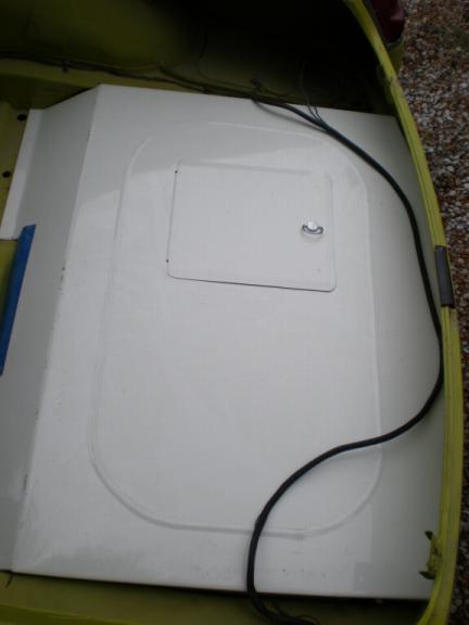
Now, we start putting everything back in the engine compartment. Additionally, like I stated previously, we've also been working in the GT hatch area, removing all the unnecessary metal supports for the hatch floor. These photos show some of the lightening tricks we've utilized. Lots of weight gone from back there.
Not including the heavy wooden GT floor, the aluminum and steel we've removed from the hatch area weighed about 20 pounds! And there's more weight to be removed from both inside and under the rear of the car!
7 December 2004: Labor, labor, labor! We moved the car inside Sunday afternoon so we could continue to work even though its rained for more than 48 hours straight without stopping.
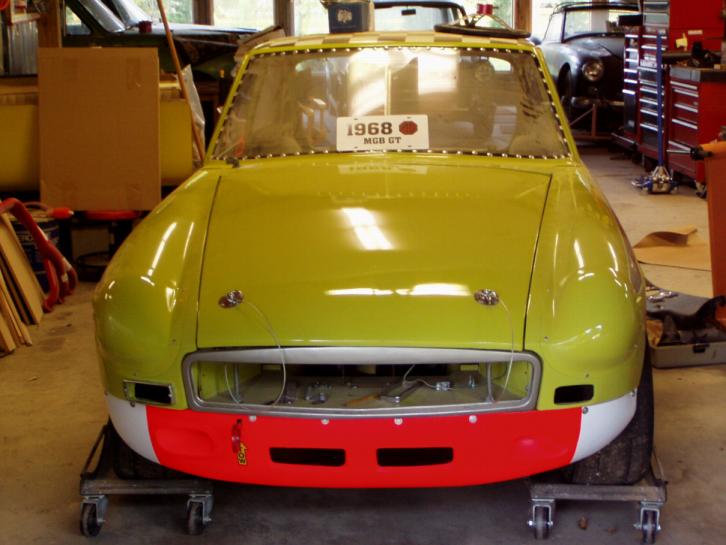
As we continue to work with the wiring harness, we'll also move the ignition switch from the steering column to the dash itself. Actually, in addition to instruments, the only switches on the dash will be a headlight switch, a horn push, a radiator fan switch, a fuel pump switch, and the ignition switch. Its a race car! There'll be no stalk switches on the steering column. 13 February 2005 Well, I'm still in Kansas, a friend is working on the body, getting it ready for paint. Here are some of his photos:
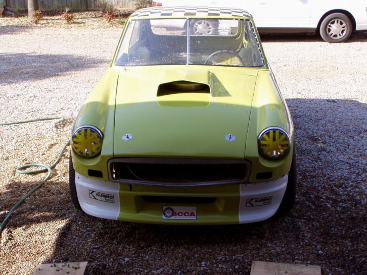
16 March 2005: In case you've been wondering where I've been, after 5 weeks in Kansas I was home for a week before taking off for Germany. That pretty much shot January, February, and most of March! Well, I'm home now; and the little car is also home. Oh, my trip to Europe was great: good German food & beer (lots of it), and good times with our wonderful young soldiers stationed over there. As for the car and the magic my friend worked on it; well. I'll let the photos speak for themselves; and MG guys will find lots of things to like or hate:
22 March 2005: So, lemme see what's happened since last we published: The neatest thing I've accomplished over the last few days is fabricating and installing the Lexan quarter windows and making the cardboard template for the hatch's Lexan window. Tomorrow I'll cut and install it. Working with Lexan isn't as hard as I thought. After visiting with a local EP SCCA racer who also owns a body shop, I came away with enough knowledge and confidence to tackle making them. From his instructions, I devised a game plan:
a. First, I made a cardboard template of the window opening. Here are a few photos:
We'll also remove the brake dust covers and cross-drill the rotors, adding efficiency and further reducing weight.
Over the past few weeks, I've also been studying rear ends and leaf springs. Remember, my '68 MGB GT came to me from the previous owner with a rear tube shock conversion. As I had no knowledge of the condition of them or the rear end, I dropped it for inspection. The tube shocks appear to be in good condition and the only thing I had to do was reverse their mounting bracket bolts so the heads were in the wheel well and the nuts were to the interior of the underside of the car. That minor modification provided an additional inch of clearance inside the wheel well as the bolt and part of the nut that extends beyond it are now inside the 'frame rails' and not extending out to possibly rub my tires. The previous owner, as I've said before, had started a restoration before I acquired the car. All the rear bushings are in excellent condition, and they are polyurethane! So, with a good, solid rear platform, I decided to figure out how to improve it. The first thing I did was drive over to Greenville, South Carolina to visit Hap Waldrop, owner of Acme Speed Shop and restorer of the remaining factory-sponsored Huffacker MGB. Hap was nice enough to allow me to spend some time looking the car over. And what I learned laying on my back on a creeper sent my mind reeling. Next I spoke with Rick Starkweather and Max Fulton who successfully campaign an SVRA MGB. Then, I spent some time discussing rear ends and leaf springs with Dave Headley of Fab-Tek, an icon in the SCCA. From their advice and experience, I developed my 'el cheapo' plan. Here tis:
In the photos below, it is easy to see the lowering affect of turning spring #1 over.
Plus, removing leafs # 5 and 6, reduced unsprung weight even more! I'll machine a couple of little 'pucks' that'll sit over the top of the spring locating bolt and fit up inside the centering hole in the metal spring perch to keep things from moving around (usually the spring pad does that). I'll also machine a couple of washers to fit between the front spring spring bushings and the spring hangers to keep the springs from twisting sideways. So, when I'm finished, the restacked springs will be clamped along their front length to keep them from curling under torque; the springs will be solidly mounted to their perches and will be held tight in the front spring mounting point. Thus, all power transferred to the rear end should be distributed directly to the tires. Labor, labor, labor. And some old pieces of metal and hose clamps.
4 January 2006: Over the last few days, I've been following Colin Chapman's "add lightness" edict. After restacking the rear leaf springs, I spent days removing all the undercoating in the wheel wells and cutting out everything under there that's not needed: the rebound strap brackets, exhaust hangers, the single plies of body metal - if it could be cut off, it was. Plus, I cut the rear bump stops in half. Then, while waiting for the new gunmetal grey paint in the wheel wells to dry, I turned to the engine compartment to "add lightness". The radiator support just didn't do it for me. Plus, Max Fulton, Crew Chief for #133, the yellow MGB of the B-Stingers SCCA Race Team, had recently told me I needed to add rigidity to the front body. So, I looked to the radiator bracket to help me in that area. Out of thin aluminum sheet, I cut a new radiator bracket. I then welded a 1/2" diameter aluminum rod to the top of it with brackets that can be bolted through the inner and outer fenders.
Not only did I add rigidity, I also cut 1 pound of weight out of the engine compartment with this new radiator bracket. Plus, my aluminum welding skills are improving!
28 January 2006: Well, the entire front suspension has now been taken apart, inspected, cleaned and painted, and reassembled. Man, its almost too pretty to cover up. The photo below was taken while I had the calipers on the bench for cleaning.
11 February 2006: Okay, everything you ever wanted to know about MGB rear ends and some you didn't.
Dave Headley is an expert in hybrid differential casings. He uses Salisbury wire axle ends welded to banjo wire casings much like others who've gone before him. If its good enough for Huffacker and Headley, its good enough for me. So, we took our Salisbury differential casing and cut the ends of the tubes off. Next, we took an old banjo differential casing that was laying around and measured for axle length and whacked its ends off. Then, we welded the Salisbury ends onto the banjo casing. Now, it wasn't as simple as that. There was some machine work to do to turn the outside dimension of the banjo casing down after it was cut so the Salisbury ends would slid over it (the Salisbury inside dimension also had to be turned down so the banjo would fit properly). We also built-in a little negative camber to ensure the wheels would maintain maximum rubber on the road during auto-crossing since, at the factory, they were built with 0 camber. My hybrid casing now has 1/2 degree of negative camber at the axle end which works out to 1-1/2-degrees at the road. Everybody knows the Salisbury differential casing is wider than the wire differential casing: 48-1/4" to 46-1/2". That's to make up for the difference is size of the Rostyle and wire wheel hubs. Old racers knew they could get more room for wider wheels if they put Rostyle hubs on wire wheel axles. Lots of people think you just switch out the axles themselves to convert from Rostyle to wire or vice versa. Certainly, you can put Rostyle axles in a wire wheel differential or the other way around since either hub works on either axle. However, there are some problems with doing that. The wire wheel axles are shorter than the Rostyle axles; so, if you put a wire wheel axle in a Rostyle differential, you'll not have as much depth where the axle spline meets the differential gear (not as much of the axle will go into the differential as if it was the correct axle going into the correct differential). Conversely, if you put Rostyle axles in a banjo differential, the axles themselves will protrude through the differential gear and almost touch one another.
Now that I've also sorted out the spring setup, I'm looking at how to continue reducing unsprung weight. This is a purpose-built race car; thus, comfort isn't part of the plan. With that in mind, I tossed the spring pads along with the spring locating plates and will bolt the rear end directly to the leaf springs. To do that, however, I had to devise some way of centering the axle on the spring using only its built in perch and the shock absorber bracket. Again, Dave Headley came to my rescue with some of his inexpensive tips (you guys HAVE to spend some time with him!). The hole in the differential casing spring perch is much larger than the spring locating bolt; the same holds true for the shock absorber bracket hole (it sits under the spring locating plate into which a rubber pad is inserted.. That's because the rubber spring pad usually surrounds the bolt on either end, All that was necessary was to machine a couple of small 'pucks' that fit over the bolt and secures it to the larger holes in the differential spring perch and shock absorber bracket.
From Dave, I also learned that, even with poly bushings, there's still some room for spring twist. So, He's devised a simple little washer that fits over the poly bushing and strengthens the spring to spring hanger connection (& it fills up the tiny space between the poly bushing and the spring hanger. They're not hard to make if you've some old pipe laying around, a good band saw, and a lathe (or, you can buy them from Dave).
18 February 2006: The rear end housing is permanently mounted under the car. The hard brake lines are run. And the 3rd member is clean as are the axles; tomorrow, I'll install them. I'm still concerned about weight - especially unsprung weight - so, today I worked on modifying the rear brake backing plates. Those things weigh 2 pounds apiece. First, I drilled a series of 1/2" and 5/8" holes around the circumference of the backing plate; then, I removed the lip that extends out beyond the brake drum. The photo below shows what I did:
8 September 2006: It's been a bit and I've put the car on the backburner due to other projects/trips. As most of you know, I spent 5 weeks in Hawaii during June and July. But, this week, I got back on the car. Here's what I accomplished this week: floors cleaned and painted and steering column reinstalled.
2008: So, now, after flirting with various venues, we've decided to go historic racing. We can now do some things the way we really wanted. First, though, we've got to make her legal and that will entail redoing some things we've already done.
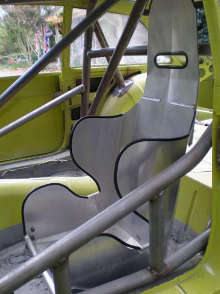
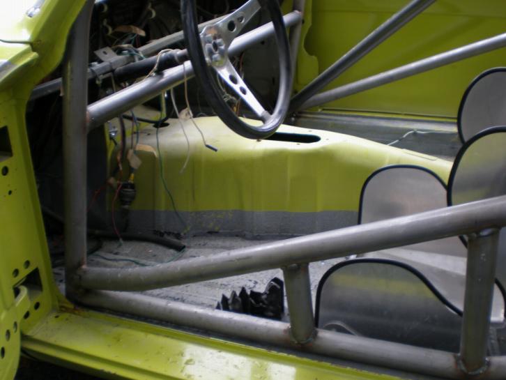
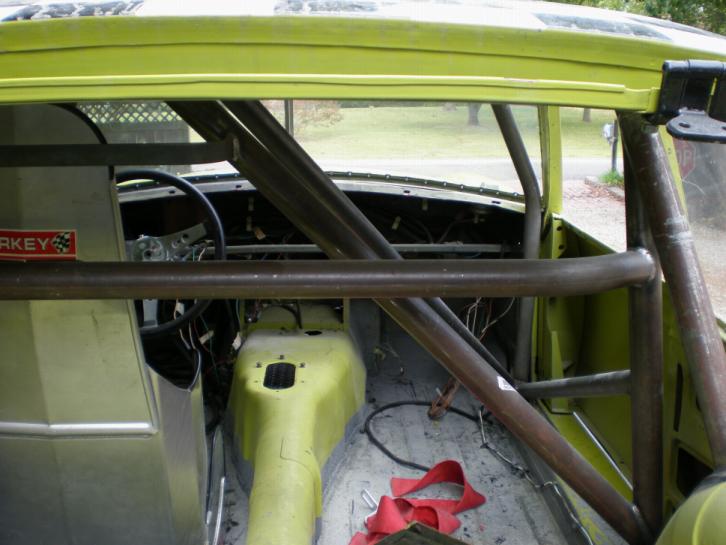
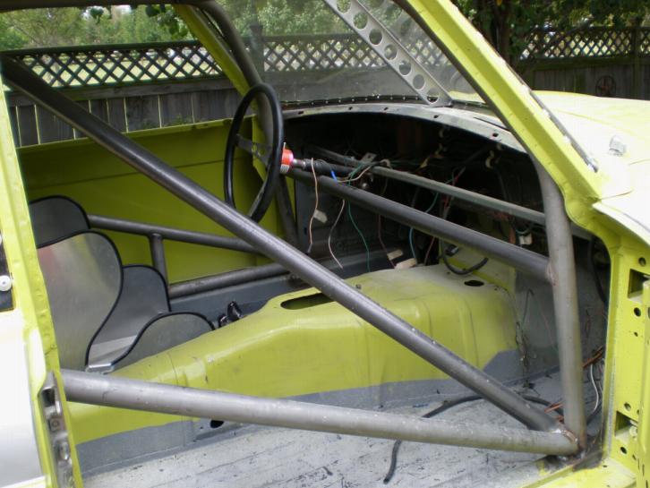
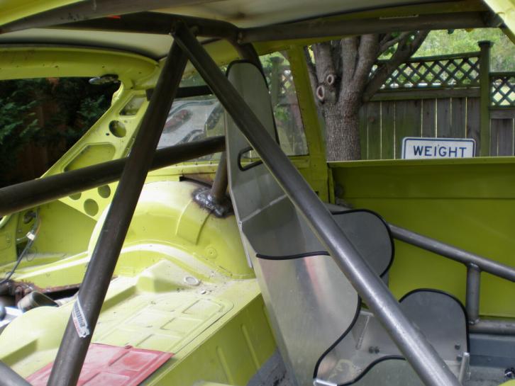
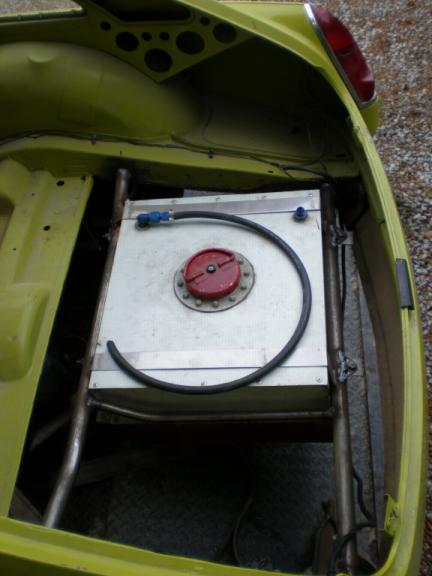
The OE MGB electric cooling fan was removed to be replaced by a lighter Hayden electric fan mounted directly to the front of the radiator. We also removed the GT headliner and painted the inside of the roof flat white in preparation for installing a full roll cage kit purchased from Autopower Industries out in California. While we're installing the roll cage, we'll also weld OE motor mount brackets back in the place of those we had to cut out of the car to install the V6 engine. And the roll cage and fuel cell are in.
More to come shortly as we start working
on her again.
|