|
|
|
A former Lucas engineer once told me that BMC would approach Lucas with a new car and a fixed amount allotted for the electrical system for each car. Lucas provided that system for the money BMC wanted to spend. Lucas takes a lot of criticism, much of it unjustified. Their products were reflective of what the manufacturer wanted. Higher end cars got better components. The lower end cars, MGB's, TR's, Healy's, etc. got more budget conscious components which actually were pretty well designed, and many were downright ingenious.
One of my LBC's is a 44 year old MG Magnette ZB Varitone. The wiring and devices all still function correctly and the
electrical problems I resolved were all caused by a PO not being careful
when he took things apart. Many of our beloved LBC's were not high end
cars, rather, they were low cost sports cars designed to give a maximum of
performance for the most money. So, don’t start out by blaming Lucas;
they did a good job for the money. One site that I strongly recommend you check out is Rick Astley’s website at the Scions of Lucas web page. Rick has done an incredible job of explaining and illustrating MGB electrical systems along with diagnosing and repairing problems. His site can be found at: My hat is off to him for the time and effort he’s put into making this information accessible to us.
Power can
be thought like water in a hose. Voltage is the pressure (volts/psi) and
current is the quantity (amps/gpm). Voltage is measured in parallel across a circuit from positive to negative. Current is measured in series with a leg of the circuit.
Resistance
can be measured both in parallel and series but for our purposes most
resistance checks will be in series. Multimeters come in two basic configurations: analog and digital. Either will work just fine and it’s just a matter of getting comfortable using the type you have. Analog meters have a needle movement where the value is read against a printed scale. Digital meters read the value being measured directly by displaying a numeric value on an LCD screen. Older digital meter used LED readouts but are essentially the same.
Digital
meters are by far the most popular and have pretty much supplanted the
analog meter although analog meters still have their uses in unique
situations. For our purposes we are assuming you’ll have a digital meter
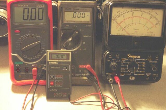
since they’re cheap and easy to use. There are two main types of digital meters; the type that requires you to manually set the scale and the auto-ranging type which does it for you. Again, either will work fine. I prefer the auto-ranging meter because a) I’m lazy and b) I use meters a lot. Like every day. Like many times a day, every day. Shown below are four of my group of a dozen or so meters. The Triplette is my garage meter for use on the MG's. The little Tenma stays in the glove box for emergencies. We use the venerable Simpson for special tasks. Last but not least, in the middle, is my trusty 20 year old Fluke. Grubby, tough, faithful, accurate, my favorite.
Picking up a good meter is not hard. The preferred meter for most electrical enthusiasts is the Fluke (as in John Fluke). These meters can be had for cheap on eBay and in pawn shops. Radio Shack sells a nice looking little auto ranger for about $30.00 that looks like a Fluke product. There are many brands out there of good to excellent quality, Triplette, Beckman, Simpson, B&K, Tenma, the list goes on and on. Pick one your budget is comfortable with. Also, pick one you can see the display on. My Triplette has a huge display that I can see from the other end of the car. It was on sale for under $30.00 and although it’s not auto ranging it’s still easy to use. So, let’s get going and use the meter to solve our electrical woes. Scale
Settings Multimeters have different settings for reading voltage, current, and resistance. Usually, there are more scale choices for reading voltage than current. Voltages scales on a multimeter can vary but a typical scale range would be 0 - 2 volts, 0 - 20 volts, 0 - 200 volts, and so on. If you have an auto ranging meter then scale setting is not necessary but if not, then the correct scale should be selected. The important thing to remember is to use a scale on the meter that is higher than the voltage to be measured. For instance, using the 0 - 2 volt scale will not give accurate readings when trying to measure automobile circuits that are about 14 volts so you would want to have the scale set to 0-20 volts. Meters can be set to measure DC or AC and often have separate scale areas for each type of voltage, DC or AC. These separate areas are often designated on the meter face by a V- (V with a dash after it) for DC and a V~ (V with a tilde-looking symbol after it) for AC measurements. Automotive circuits are almost always measured as DC. Household wiring would require the meter to be set for AC measurements.
Multimeters usually only have two choices for reading amps, a low selection and a high selection. The lower selection generally reads to about 300 milliamps (“ma” or .3 amps), Smaller multimeters on the higher scale will usually only read up to 1 amp of current. Higher priced meters will read up to 10 amps. Even so, the lower reading can be very useful for finding those pesky current draws that kill batteries. Using the multimeter: To read voltage select the scale, place the red lead on the positive point to be checked and the negative lead to ground. Be sure that the negative lead is indeed making a good contact with the car body ground. Test this by checking a point you know has a positive voltage such as the bottom fuse on the fuse box where the brown lead is connected. If you get a good reading then your meter’s ground lead is making a good connection. Another good place to test is across the battery terminals. Place the red lead on the positive post and the black lead on the negative post. You should read around 12 volts DC. If you start the car and repeat the test you should read almost 14 volts DC. This confirms that your alternator is working. An important part of finding and repairing problems in the electrical system is having the correct wiring diagram for your car. While both the Bentley and Haynes manuals have diagrams I prefer the Haynes since they are more year-specific and laid out more to my liking. Take the Haynes to your local office supply store and have a copy made of the diagram for your car that is the maximum size that they can make. Also make a copy of the device numbering page that tells what device the number on the diagram refers to. Wiring diagrams may be intimidating upon first glance but look over them for a while and you’ll see that they are pretty straight forward and not hard to understand. The most tedious part of using a diagram is following the lines around; that’s why you get the big copy. The diagram is necessary to troubleshoot in a linear manner which takes the guesswork out of solving the problem. Troubleshooting using voltage drops:
Often, on
cars that are 30+ years old, circuits suffer from age and corrosion
causing lights and other equipment to not function correctly or to fail.
Many times it is possible to easily find the source of the problem by
looking for a drop in voltage as the voltage progresses through a circuit.
Usually, the problem will be solved when a poor connection is uncovered,
be it a snap connector or a corroded terminal. There is a condition that
needs to be kept in mind when using the voltage-drop method of
troubleshooting. That is this: a circuit drops voltage across a poor
connection, or resistance, proportional to the current that is being drawn
through the circuit. This means that the voltage drop across an unloaded,
i.e. no current being used, circuit will be small or non-existent. The
voltage drop will increase greatly, however, when the circuit is put under
a load, as in when the light or electrical motor on that circuit is turned
on. Here’s
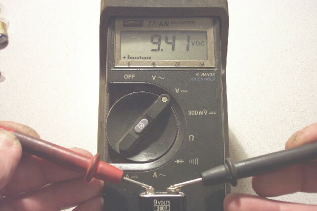
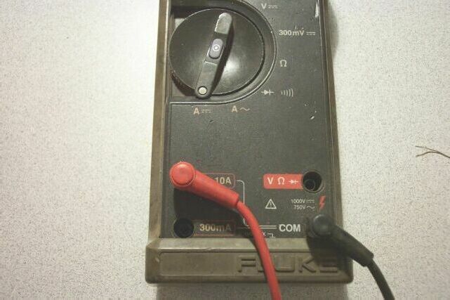
an example: My MG guy was a British Leyland mechanic for a number of years and has had a Brit car shop of his own since the demise of BL. He knows just about everything about Brit cars there is to know, except, he is intimidated by the electrical side of things. Recently, he was puzzled by the right front turn signal on a RB MGB that was not working. I whipped out my trusty Fluke 77 meter and went after it. First I found a good ground for my meter. This cannot be stressed enough; you can chase your tail for hours if your meter is not grounded properly. The black meter lead was placed on an engine bolt and the red lead placed on the lowest fuse in the fuse box which always has power. I read 12 volts, so I knew the black lead was grounded correctly and that’s where my black lead would stay during this test. Now I could continue. I turned on the turn signal switch then started working my way, trying to do things in a linear manner, back from the light. I took the bulb out and checked the light fixture with the red lead and found 12 volts present. The bulb went back in but still would not light. I knew the bulb was good because I used the ohmmeter to check it. More on that later. I traced the wire back until I found a snap connector in the engine compartment. I stuck my meter lead into the snap connector on the light fixture side of the connection, no voltage. I then stuck the lead into the other, or supply side, of the snap connector and viola! voltage. I pulled the two bullet connectors out of the snap connector and touched them together and the signal worked fine. With the bulb out, I measured good voltage on both sides of the snap connector. With the bulb in, and trying to draw current, I had no voltage on the bulb side of the snap connector. Obviously, the snap connector was the point that was causing the voltage drop. It was replaced and the problem was solved. The circuit must be under a load (i.e. the device is turned on) to find out where the bad connection is located. A corroded connection will show good voltage if it does not have a load on it. Looking for current draws: To read current you need to set the meter differently. All meters have a separate socket for the positive, or red, lead of the meter to plug into and a selection on the meter’s switch for DC or AC amps. On many meters, this socket is where you choose the lower or higher current scale. The negative leads stays in its normal socket. When you are ready to read current, you must place the meter in series with the circuit. This requires that you interrupt, or break, the circuit to place the meter in line. Choose a point where a connection can be undone, such as a snap connector or a terminal that can be removed or across a fuse holder with the fuse removed. Then put the red lead on the battery side of the circuit and the black lead on the load side of the circuit. Here’s the Fluke set up to read on the 10 amp scale:
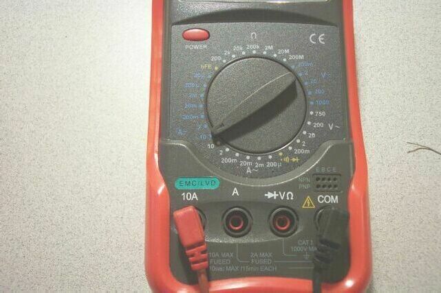
Here’s the Tripplett set up on the 10 amp scale:
Here’s an example of using the ammeter: I want to find out why my battery keeps going dead after several days. Because it takes several days, I assume that the current draw is not really high, maybe less than 1 amp. A word of caution here. Always start at the highest level that the meter has for measuring current. Most meters are fused on the lower level but I’ve burnt meters before by measuring a high current on a low level setting. I set my meter lead into the socket labeled “300ma”. This will allow me to read up to 300ma or .3 amps. I select DC amps with the selector on the meter. Then I remove the positive terminal on the battery. I hook the red lead to the positive terminal of the battery and the black lead to the positive cable going to the car. By doing this, I have inserted the meter in series with the circuit and am now reading how much current is flowing into the car’s electrical circuits from the battery. My meter now reads 300ma., the maximum for that scale. Hmm, maybe I better check it on the higher scale. I switch the lead on the meter to the 10 amp socket. Now my reading is 560ma. That’s better. I know that 560ma (more than ½ amp) is too much. Now it’s a just a linear troubleshooting progression. I start removing fuses from the fuse block while checking my readings. When I find that the fuse in the ignition circuit is removed, my current reading goes to less than 25ma. Something in the ignition circuit is not right. I replace the fuse and start moving down the circuit, breaking it at different points to see if my 560ma draw goes away. I unplug the ignition switch and the meter goes to 23ma. It’s probably a bad ignition switch that is keeping the ignition circuit grounded when the switch is off. Identifying the circuit that is causing the excessive current draw is the first step. Then it’s a case of just going down the circuit until you find the problem. If you use a logical, point a, to point b, to point c, method it keeps you from hopping all over the place and will solve the problem faster than randomly trying to troubleshoot. Let the meter do the work. Remember, you must place the meter in series with the circuit so the current will flow through the meter in order to read the current. When we say “in series” we mean that the circuit, or wire, will be interrupted or disconnected, and one of the meter’s lead will be hooked to one end of the wire and the other meter lead will be hooked to the other end of the wire. For instance, if you wanted to know how much current your fuel pump was consuming, you would pull the white wire from the pump, hook the meter’s red wire to that white wire and hook the meter’s black lead to the point from which you removed the white wire. Be advised that very few meters can handle the total current flow that occurs with all the electrical devices in a car turned on. The headlights will pull about 6 amps each and the rest of the lights will add plenty of current draw to that. So, don’t try to figure out how much total current is being consumed by the car’s electrical system at once. Do it one circuit at a time. Believe me, you can’t read the starter’s current draw with any meter that you would normally own. One method that can save a lot of grief when installing a new harness is to use an external 12vdc power supply to power up the electrical system so you can test things. I did this on my '73 roadster and it saved me from cooking the harness. I pulled the new harness into place but someone else hooked up the dash harness to the main harness. I never trust electrical connections I didn’t make myself so I used a 10 amp power supply hooked to the battery cables in place of the actual battery. The cars battery can supply more than enough current to fry wiring if it is shorted. My 10 amp supply will shut off if the current exceeds 10 amps. I hooked my meter, set to read amps, in line with the positive cable so I could read the current flow. Right from the start I found two connections that were wrong because the meter indicated current flowing with nothing turned on. These connections turned out to be hot leads plugged directly into a ground connection and would have fried the harness if I had used the battery as my current source. Checking
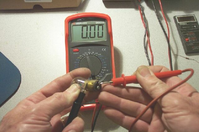
continuity or, using the Ohmmeter: Using the ohmmeter portion of a multimeter can save a lot of time and frustration. On non-auto-ranging meters you set the scale to the upper end of the resistance value you wish to measure. I usually set mine on the 20K (or 20,000 ohms) scale since anything beyond that much resistance means the circuit is open, for all practical purposes. An ohmmeter measures the resistance of a circuit by passing a small amount of current, supplied by the multimeter’s internal battery, through the circuit. Set your meter to ohms, on the 20K scale and touch the leads together. The meter should go from no reading to a reading of zero, or close to it. Now hold a lead with your thumb and forefinger of each hand. You may have to increase the scale since the body will show a resistance of about 300K. So now you know what a short circuit (zero ohms), an open circuit (infinite ohms), and a resistive circuit (your clammy hands at 300K) look like. Many meters will have a diode test on them. This function is useful since the meter beeps when it sees a short, or zero resistance, circuit. Very helpful if you’re poking around and can’t see the meter face very well. I use it a lot. There are several very useful checks you can do with the ohmmeter. Checking bulbs, fuses, and sections of wiring are the most common. Here the meter is set to 20k ohms checking a good bulb:
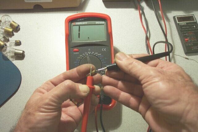
It can be difficult to tell if a bulb is good by looking at it. I can’t see those filaments like I used to. Check the bulb by placing one lead on the metal body of the bulb and the other lead on the contact that supplies the positive voltage to the bulb. Zero resistance means the bulb is good. Easier and faster than hunting up another bulb and installing it. I found several bad bulbs this way on my recent restoration. Checking and finding a bad bulb:
Fuses also can fool you. Fuses don’t generally age but on occasion the element inside will break due to vibration. This usually happens just inside the cap where you can’t see it. Use the ohmmeter the same way you checked the bulb to confirm the fuse is good. Just because the element isn’t fried doesn’t mean it’s good. Open wires in a harness can cause no end of grief. I’ve seen it happen where a circuit opened up for no apparent reason and short of cutting the harness open to examine it there no way to know what the cause was. To test the harness in these situations you need to build a long clip lead to assist you. This is a good idea for another reason and that is so you can ground the black lead to a good known ground point with your long clip lead and move around the car to make measurements without having to find a new ground point. I built one about 10 feet long with a scrap piece of 16 gauge stranded wire and two alligator clips. If you suspect an open wire, then find two points where the suspect wire can be disconnected. For instance, the park lamp wire to the rear could be checked by unplugging the red lead at the fuse block and the snap connector on the red wires in the trunk. Put one end of your long clip lead on one end of the red wire and bring the other end of the clip lead up to the engine bay. Clip the black meter lead onto that clip lead end. Then put the red meter lead on the red wire and see if you have continuity. In essence, you’re just extending the reach on one of your meter’s leads. Here’s an example:
I wanted
to find out why the interior light didn’t work on the Magnette. I
suspected that it had to do with one of several wires that the PO
disconnected in the engine compartment and left hanging out loose. But
which one was the interior light wire? I hooked the long clip/meter lead
to one of the loose wires in the engine compartment then checked the wire
feeding the light. Nope, the circuit was open. I moved the clip/meter lead
to the next wire and checked the interior light and bam, that was it.
I
also found out why it was disconnected. I measured the resistance, to
ground, of the wire feeding the light. With no bulb in the fixture there
should be no circuit to ground, but there was. That’s why it was blowing
fuses. I took the fixture cover off, the PO had plugged the wire feeding
the light into the wrong socket, grounding the wire. A word of caution: If you measure a light circuit’s hot wire to ground with the ohmmeter it will read a short since the circuit goes through the bulb filament to ground. To see if a light circuit’s hot lead is shorted you need to remove the bulb while you test the wire. A multimeter is one of most useful tools you will ever have. Once you’ve messed around with it you will find more uses for it than you could ever imagine. There are things you can do with it that you just cannot do with a test light. The continuity, or resistance, test is an extremely useful test for troubleshoot our LBC’s electrical problems. The voltage drop test method can save you hours of work. With the multimeter you can find the problem without swapping parts and possibly burning a new part up. Start out by making a few measurements with it to get familiar. Test some bulbs and fuses. Check the voltage at the fuse box. Check your battery voltage with the engine running and with the engine off. The more you play with it the more comfortable and confident you’ll be with it. I’ve tried to explain some of the uses for a multimeter. Since I’ve used them most of my life I may not have explained their function in a manner that makes the most sense. If you have any questions or suggestions drop me a note at wraylemke@compuserve.com. Safety Fast |