|
|
|
|
Installing a 1964 MkI Dash in a MkII car Installing Servo-boosted brakes in a non-boosted car Body Preparation Installing Fresh Air Vents |
terior chrome/stainless ordered from Moss--not gonna use any used pieces on the exterior!! 4
September
2001:
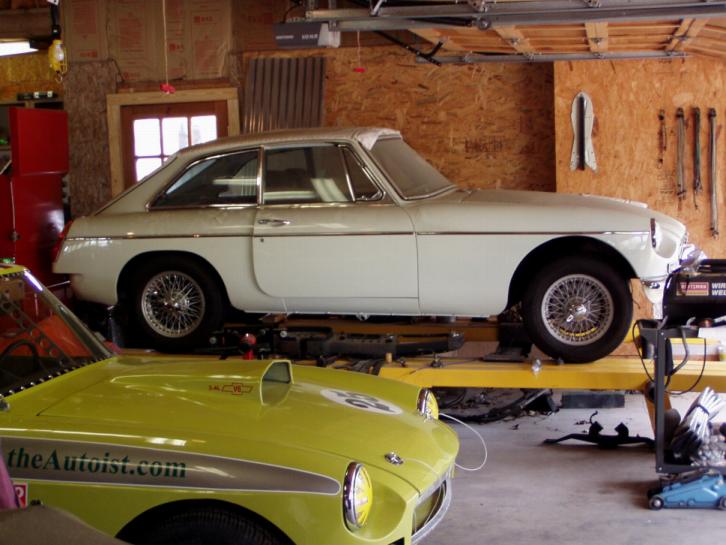
Well, it rained all
weekend so I was able to spend some quality time in the garage moving all the
cars around, cleaning, organizing, etc. I also accomplished several things
on the little Glacier White MGBGT: Plus, I sorted out all the pieces & parts to determine what would be reused & what would be replaced. Here's the point in a restoration where you should build a table next to the car where you can lay everything out in plain sight. That way, you can compare trim pieces, etc to one another to ensure the same quality. Man, that doubles my Moss bill for this month!! You might ask, "Why's he doing all that fluff stuff when the suspension has to be changed, the fuel tank installed, the plumbing & wiring rerun, not to mention the engine & transmission?" And, you would be correct in asking. All I can say is: "Wife." Its her car & she needs to see progress. To a woman, progress means it starts looking like a car. They don't look underneath or in the engine compartment. I do enough 'fluff stuff' to sufficiently impress Jerri when she wanders into the garage; & now, I can return to my other projects until "parts arrive." 2
October 2001:
Since the last time I posted, here's what's been done. Oh, as I said
earlier: every piece of
bright work on the body is or will be brand new: Next, it's installation of the new rear split bumpers & door window mechanisms/guts. Remember: I've gotta make it look like a car so Jerri can see the progress...she'll get antsy when she doesn't see anything happening while I'm plumbing/wiring it. Every day she walks out in the garage and asks, "When can I drive it?" 16 October 2001: After we got back from our cruise, I spent some time aligning & installing new split rear bumpers. I used all new hardware on the bumpers & rebuilt/painted brackets & tag lights. Also installed new stainless corner filler plates above bumpers. 13 November 2001: Well, didn't get it out of the garage as there's a rubber bumper Midget that's dead in the water behind it. However, since last month, I've accomplished the following: 1. New drip rail mouldings
(Moss #'s 472-710, 472-715, Several other assemblies have also been rebuilt/repainted (heater, master cylinders/pedal box, radiator & support, oil cooler, battery cover) & are ready to go in the engine compartment once the wiring/plumbing is completed. The front suspension cross member is stripped & primed & I've made some modifications (additional grease zerts) to it in preparation for rebuild...more to come on those mods later. Except for the front bumper, grille, & door guts/vent window assemblies, the body is pretty much completed. Jerri likes it!!
6 December 2001: Since I'm building a completely "emission-controls free" car, I won't be using the carbon canister evaporative loss system. So, while I was sandblasting and stripping the car, it seemed to be a good time to also do away with the fuel return system connected to the carbon canisters. That also means I can't use a vented gas tank. So, I ordered--& received--a new non-vented gas tank for a 1965-69 MGB/GT (Moss #4 56-815). I also ordered a new packing strip set (Moss # 280-300), a gas tank mount hardware set (Moss # 323-628), a new sending unit (Moss # 360-660), and new locking & sealing rings (Moss #'s 360-665 & 293-410). Another tricky item is the car's locking system. As I'm using a '67 steel dash, I have to have that dash lock set because of the glove box. So, I ordered a complete new Master Lock Set for a '67 car (Moss # 401-588) that includes the glove box lock, both door locks, and a new hatch lock. New vent window frame seating seals (Moss #'s 282-770 & 282-780) with new felt flex channels for door glass (Moss # 458-610), and new vent window corner blocks (Moss # 282-575 & 282-595) were ordered. The next thing is to build the doors: vent windows, regulators, handles, etc. After that, its jack her up & begin the plumbing/rewiring process while I rebuild the suspension & install the new fuel system (Oh, I've started adding Moss or Victoria British parts numbers for the new items I've ordered since some of you have asked for that information. I'll go back throughout the restoration process & add them as I get time.) 17 December 2001: Last week I read an article about the handling characteristics of the MGB and how to improve them. One thing about the brake system that caught my eye was:
"Well," I thought. "I am building a car for a lady. She'll never push it I'll probably never even drive it; and, my 1979 MGB that's undergoing a V-8 conversion has an excellent servo-boosted brake system that I'm going to remove to achieve better feel and stopping power. Wonder what would happen if, hmmmm..........." Reading on, I found:
So, my plan is to use my '79 B's servo-boosted brake system on Jerri's '70 GT. As I said earlier, I'm taking it off anyway so this just makes sense. The other thing I'm working on is
the wiring harness. Combining all the different things from various year
models like I am will probably cause a wiring nightmare (&, I haven't even begun the
wiring yet). So, I contacted Lesley
at British Wiring (20449 Ithaca Road
- Olympia Fields, IL - (708) 481-9050) to help me with a custom-built
harness. After discussing my specifications with her factory in the UK, it
looks like that's the way I'm going. More
on the wiring harness as we work out the details.
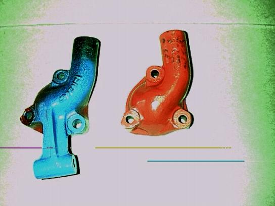
Over the holidays, in addition to Christmas, New Year's, and the flu, I've gotten a bit accomplished: 1. Installed Ian Pender's gas strut modification kit on the rear hatch. It makes opening the hatch an easy 1 hand job for Jerri, and it only took about a half hour to install. 2. The driver door is completely assembled (window mechanism, vent window, handles/locks, etc.) with factory tinted glass. I'm tackling the passenger door today. 3. The engine is painted red & ready for installation as soon as I've sorted out the engine compartment. Oh, I also modified the Water Outlet Elbow. You know the one: it has the bracket for the air pump sticking out on the alternator side of the engine...&, those air pump brackets sure look silly hanging out there with nothing on them So, I got my trusty air grinder out & whacked the sucker off!!! Then, took my grinder & sander & shaped the whole thing to look like there never was an air pump bracket on it. Now, it looks like the earlier '62-'67 rounded ones but the elbow faces the proper direction for the 1970 radiator. Painted it red & put it on!!! Really looks good with the aluminum valve cover I'm using. Here's a before & after photo.
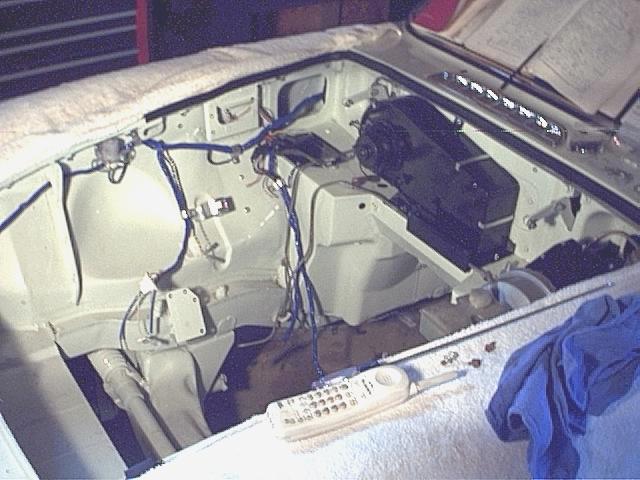
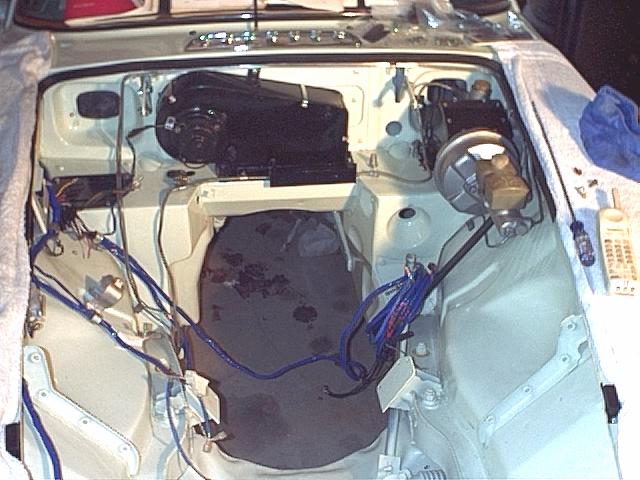
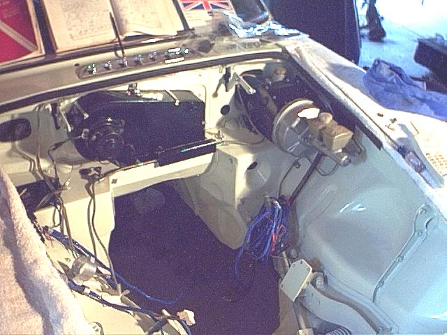
(Oh, while I was painting, Jerri pulled into the garage & exclaimed, "Wow, that looks great!! Will it keep that nice shine?" as she walked over to the table on which the engine sits to inspect it. "That's gonna look super in my white car." She'll never open the hood!) 7 January 2002: Well, got the passenger door built up. Now, the only thing left on the exterior of the body is the front bumper, grille, & right rear split bumper. The RR bumper has to be rechromed. So, while British Wiring is building the harness, the next item is converting the car to a servo-boosted brake system out of my '79 V8 car. 14 January 2002: Spent the weekend sorting out & beginning the conversion to servo-boosted brakes. I'll use the brake system out of my '79 that's undergoing a V8 conversion & changeover to non-servo brakes. Both conversions will be covered in one article. See article. Plus, I wrote the big check and ordered the custom-built wiring harness from British Wiring. 14 March 2002: Lots has happened since the post above, but most of it has been covered in the Brake Article. There are some updates with photos to that article today also as I've got the power booster assembly installed. Plus, my custom wiring harness has arrived and, hopefully, will be installed in the next few days. 1 April 2002: Been focusing on new wiring harness over last 2 weeks. Its a beauty but figuring it out has been a slow process; not because of the quality of British Wiring's work but, instead, because of all the modifications I'm making to the car. 15 April 2002: WOW!! There are lots of little things to put back in an engine compartment after its stripped for painting: wiring harness clips, rubber grommets, heater, accelerator cable guide, oil pressure pipes and connector, fuel line, clutch master cylinder line, coil mounting bracket, windshield washer pump, clear tubing & container assembly, battery cut-off relay, and all new nuts, bolts, washers, etc. She's slowly looking like a working engine compartment again. Heck, installing the engine will be a snap after all this.
10 June 2002:
As I move along with the little car's restoration, one of the things I plan on
doing is putting fresh air vents in the steel dash where the radio normally
goes. That will give Jerri some air on her face. To follow along
with this modification, you can jump over to Installing
Fresh Air Vents. Several friends have asked me to outline the
modification as they also want to install these vents. |
|
21 April 2003: WOW! I've let the little car sit for almost a year while I played with other things. Shame on me! So, here's today's story: I rented a 34' Champ Lift to stand the trusses on my Garage-Mahal extension over the weekend (figured I'd get them standing Saturday & drive down to Birmingham to spend Easter Sunday with daughter0. As usual, my luck is bad - damn thing had a short in it! After several hours, the mechanic took it back to rental place. So, I wasted the morning and part of early afternoon on that gadget. Should've just stood the trusses by hand! So, I walked into my garage and
was drawn to the little GT. She's just sitting up on my Kwiklift rack. I had another suspension beam sitting under the car so I finished stripping it of its components, cleaned it, and painted it black. Then, I rebuilt the lower wishbone/control arms and painted them black. Oh, we also modified the wishbone arms by installing zerts in their big ends so the wishbone shafts can be greased; and, new V8 bushings went in the assemblies. Then, I purchased new grade 8 bolts, washers, and nuts to attach the wishbone assemblies to the beam. Next, I turned to the car itself. The first thing I needed to do was jack the car up to remove its tires so its old beam could be dropped. Now, this lift has moveable 'saddles' spanning its 2 ramps that are used to position jacks so the car can be jacked up off the lift. To do the jacking, however, I had to use the car's jack points and its jack. And, that presented a problem: both jack points were flattened out so the bar of the jack wouldn't go in them. Several hours later, both jack points were round again and the jack fitted as designed. How did I do that, you ask. Well, I started with the smallest pipe I could force into the flattened opening and worked incrementally upwards until a 3/4" pipe would slide easily into the jacking point. All the while, I applied heat to the jacking point so the metal would contour to the pipes while hammering on the outside of the jacking point itself to help the metal remember its original shape. Now, some flat black paint can be applied to the jacking points (I was gonna do that anyway as they are Glacier White now). So, Saturday ended with the front tires off an the car on jack stands ready for me to drop the beam. The newly repainted beam is beautiful as are the lower wishbone assemblies. Oh, I also installed the new front bumper spring brackets (Moss #'s: 472-210 & 472-220) using new hardware (Moss Mounting Kit #321-938) mainly to have something to hold onto as I pull myself up from under the car. 6 May 2003 When it rains, it pours! And I'm not necessarily talking about the weather though in this instance, it was pouring rain. Since it had rained all day, I decided to work on the car, removing the old suspension beam intact. I slid my engine hoist up under the lift & inserted its tongue through the engine compartment to grab the beam with chains. The steering rack came out easily enough as did 3 of the 4 cross-member bolts. However, the rear driver-side cross-member bolt - the one nearest the exhaust manifold - didn't budge. I tried hammering it out from on top. Nothing! So, I removed the nut from the rear of the cross-member bolt and slid the suspension out from underneath the car. Then, I tried moving the bolt from the bottom using an air impact wrench and the bolt's nut. All I succeeded in doing was stripping the nut onto the bolt! Beating with a BFH didn't budge it either way. And I really didn't want to use heat because the engine compartment is painted, so... I began with a 1/8" drill bit and worked up to a 1/4" bit. However, the extractor also didn't budge the bolt. Working up to a drill bit the size of the bolt, I drilled through the bolt halfway down into the car's frame member. Nothing! Apparently, the heat from the exhaust manifold has 'welded' the bolt into its hole. I did, however, succeed in breaking the welds on top of the frame rail that hold the bolt's spacer in place. Now, I've gotta repaint! And I still have to remove that bolt (or what's left of it!). And its still raining! 19 May 2003: So, here's the status; and, I've never faced this problem before. I cut off the bottom of the bolt and drilled all the way through it with a 3/8" bit. It still wouldn't move so I went up to a 1/2" bit. Now, the bolt is 1/2" in diameter so I stopped when I realized there was no way to keep the bit centered. However, the bolt is really frozen inside its "distance tube." I call it a distance tube as it is a round tube welded through the frame rail through which the bolt goes. With no other options, I cut the spot welds holding the distance tube strengthening plate to the bottom of the frame rail and bent the plate out of the way to gain access to the tube itself. It also was welded to the bottom of the frame rail as well as to the top. I broke all the welds and the distance tube (with the bolt inside it) dropped to the garage floor. Now, I have to make a new distance tube, weld it inside the frame rail, and insert a new suspension beam bolt. Then the driver inner fender, the bottom of the frame rail, and the driver side fender well have to be repainted. LESSON: When dropping the suspension beam, if the driver side bolt doesn't automatically drop to the garage floor after the nut is removed, remove the bottom nut and take the suspension beam out. Don't try to force that suspension beam bolt from the frame rail. Accept the fact that years of exhaust heat have welded it in place. And, when replacing it (if it comes out), use lots of anti-seize gook!
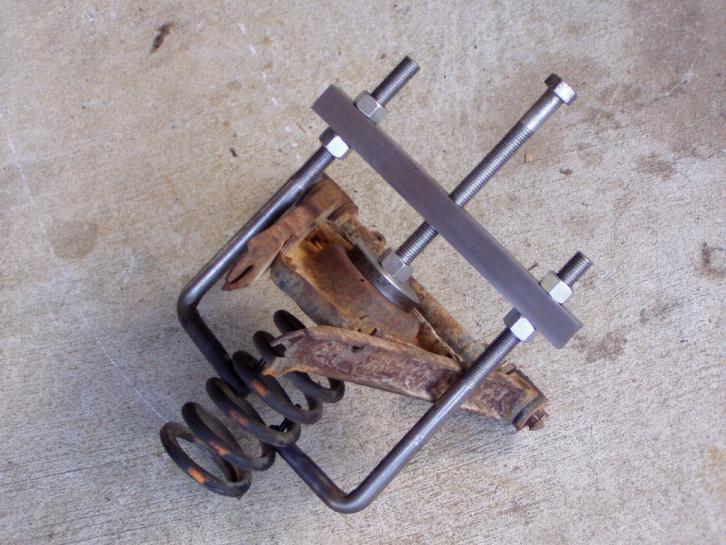
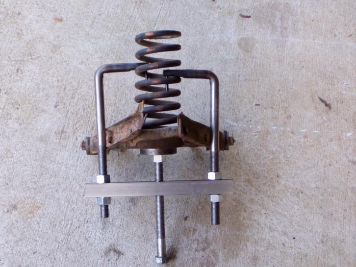
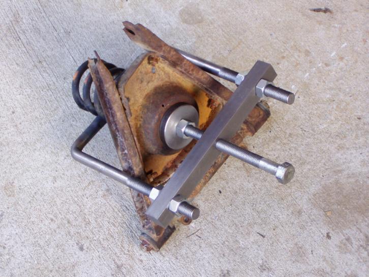
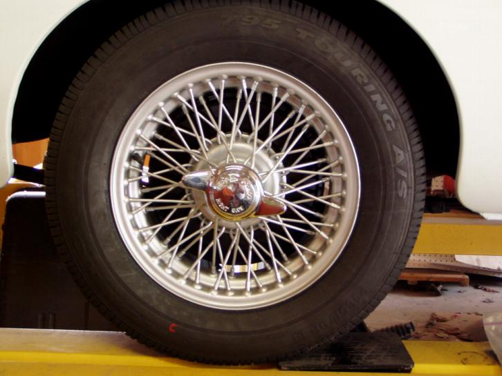
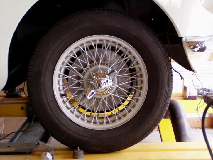
29 September 2004: Though I've not been posting regularly, several things have happened to Jerri's GT since I last updated this section: a. The new front suspension distance tube has been welded in place and the driver inner fender and bottom of the frame rail have been repainted. All the new front suspension bushings are here along with new springs, tie rod ends, kingpins, anti-sway bar links, etc. needed to build the front suspension. The suspension beam has been test fitted - the repair was successful. This weekend the build of the front suspension begins. b. I've bought new front and rear wire wheel hubs along with new 14" wire wheels. The rear hubs are under the car; the front ones go on with the new front suspension. And, man, do those new wire wheels look good on the new hubs with the new brake drums shining behind them. c. I've built a complete new set of rear brakes. They're bolted to the rear end right now. d. There is a set of new front brake rotors sitting on my bench alongside a pair of new front brake calipers and hoses just waiting for the front suspension to be built. You know, that only took a few brief paragraphs to describe. However, making the new front suspension beam distance tube and welding it in place occurred over several months of machine work. Then, I had to sand and repaint places where welding the distance tube ruined the paint. Plus, I undercoated the inside of the front and rear fenders before any suspension items were installed. And building the complete new rear brake setups on the bench took a few days (I mean, everything that has to do with the rear brakes is brand new - from the backing plate out!) And I had to hang tough through a little harassment from Jerri when she came home from volunteering at the local library and found me working on the rear end of her car. "What's happened? Is it snowing somewhere south of here? Or did you just get lost as you were wandering around in the Garage-mahal? You're working on my car: should call 911?" You guys know the routine! 3 October 2004: This weekend we got quite a bit done on the front suspension build. The newly painted suspension beam with its new upper and lower mounting pads is bolted under the car. New rebound buffers are attached to the ends of the beam. New '74-1/2 GT springs are also temporarily located under the beam as are the rebuilt lower wishbone assemblies (with new bushings on the wishbone pivot end - the new kingpins and stub axles will go on later this week). Oh, we also drilled the wishbone arms for grease fittings on the pivot end and modified them internally to accept grease. We also installed new sway bar links on the lower wishbone assemblies. 4 October 2004: Today was one of those "dirty" days. Everything from the old suspension that's going to be reused was filthy from age and use. Got the new front shocks installed and then most of the day was spent cleaning nuts and bolts; however, I did get the swivel axles disassembled and in the cleaning tank in preparation for new king pins, bearings and bushings. 11 October 2004: Since last I updated the site, I attempted to compress the new front springs to assemble the new stub axle assemblies. All I did was lift the front end off the jacks. So, I chained the car to my KwikLift so my floor jack could compress the springs rather than lifting the car off its jacks. First, however, before reattempting to compress the springs, I needed to stabilize the car a bit as all 4 corners were in the air on jack stands. So, today I had 4 new Kuhmo 185/70R14 tires mounted on the new wire wheels. The rear wheels are now on the car, held in place on the new rear hubs by a pair of new winged knock-offs; and, the rear of the car is sitting firmly on the Kwiklift ramps. Tomorrow I chain the front suspension beam to the Kwiklift and again attempt to compress the springs. 22 October 2004: Well, chaining it to the Kwiklift didn't work either. Nor did the suggestions of several members of MG-dom. So, I took a drawing of MG Service Tool
This weekend we'll see it it works! 16 April 2005: Well, it didn't! Just as the spring reached the point where I could almost fit the upper suspension link trunnion into the shock lever, the center shaft of the tool would slip. That, plus, I was worried about the outer arms slipping out of the spring itself. So, off and on, I'd try again. We modified the tool several times to no avail. I reread the shop manual to see exactly how Abingdon used their spring compressor - don't try to install a spring that way! I completely disassembled the suspension following their directions and still got nowhere. Finally, this morning I decided that the springs were going to compress or they were going to shoot out of the tool and flatten my head against the wall! Voila! Hallelujah! The springs are compressed! And the suspension is complete! New bearings and races, new seals, new hubs, new wire wheels, new king pin assemblies, new bushings, new bolts...heck, everything is new! And it only took 2 thin shims in each hub for them to turn like they were designed to do. Don't ask me what I did differently I can't think of anything. For some reason, everything just fell into place. And for the first time in a long time, I can see the light at the end of the tunnel.
22 June 2005: The new front brake calipers are installed along with the correct new front brake rotors. Along with the rotors, I also installed new front brake lines, pads and pad retaining clips and pins. 24 October 2005: Well, today I got everything lined up to start the wiring/plumbing. Yesterday, I temporarily put the dash together to ensure that all the wires matched the instrument/switch locations. Up under the car, I got everything stretched out so tomorrow I can bolt it all up with new brackets, bushings, and bolts. Plus, the new gas tank is ready to go under the car, after wiring/plumbing, using a new tank mounting kit. In keeping with the car's character, I'm using a non-vented tank. 25 October 2005: Today, I got the battery cable, brake line, and fuel line permanently run and attached to the front half of the underbody. Remember, this is a '71 body shell into which I've grafted late power boosted brakes; thus, I had to reroute the brake lines along the top edge of the engine compartment over the heater and make the connection to the underbody line right after it turns behind the firewall, a little farther forward than original. I also had to reroute the gas line over the late model pedal box to a place out along the driver inner fender as the car will have an 18V engine with dual HIF-4 carburetors; so, the fuel line has to feed the front carb first. However, I'm leaving the fuel filter mounted on the firewall between the heater and the pedal box. I don't know why I did it; however, back when I did the body, I used an aftermarket floor that doesn't have locators for seats, plumbing, etc. built in. I probably had a new one on hand at the time and it was just easier to take it to the body shop after we sandblasted the car than to wait for one to arrive from Moss. Now, however, I'm 'paying the piper' as I've got to do some drilling and welding to fit the plumbing underbody grommets and retaining straps to the rear half of the underbody. Oh, well, tomorrow's another day! Hopefully, by tomorrow's post, all will be mounted and I can turn to the gas tank. 26 October 2005: Wiring harness is finished all way back to (& in) the hatch floor! Brake line is hooked up to the rear brakes! Fuel line is run to where the new fuel pump will be located! Battery cable is back to the passenger-side battery box! And the battery ground strap is converted from dual battery setup to single battery in the passenger-side box! 30 October 2005: Finished! Wiring! Plumbing! New gas tank!
|
|
|